Usb Cable Wiring Diagram Pdf
What is a USB pinout A USB pinout refers to the arrangement of pins or connectors on a USB cable or port. It specifies the signaling and electrical characteristics of each pin to ensure proper communication and power delivery between devices.
Usb C Wiring Diagram
USB is the short form of Universal Serial Bus, a standard port that helps to connect computer peripherals like scanner, printer, digital camera, flash drive and more to the Computer. The USB standard supports the data transfer at the rate of 12 Mbps. Related Products: Connectors | Connector Other | Connector Audio and Video | Connector Power

Usb C Cable Wiring Diagram
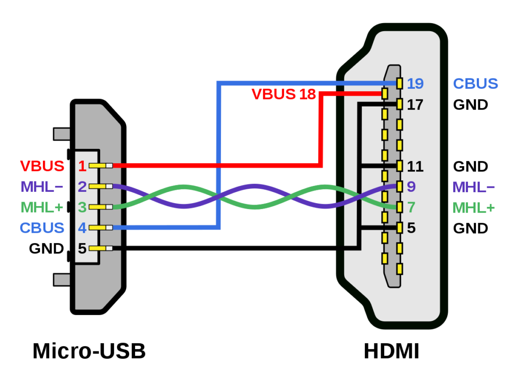
Micro USB Pinout Diagrams. Looking at the micro connector on a cable, all generations have pins numbered 1-4, ascending, from left to right on the main trapezoid. Third generation connectors have pins 6-10, ascending, from left to right, on the added side rectangle. You'll find shielded wires on these connectors, and the data wires (positive.

USB pinout, wiring and how it works!
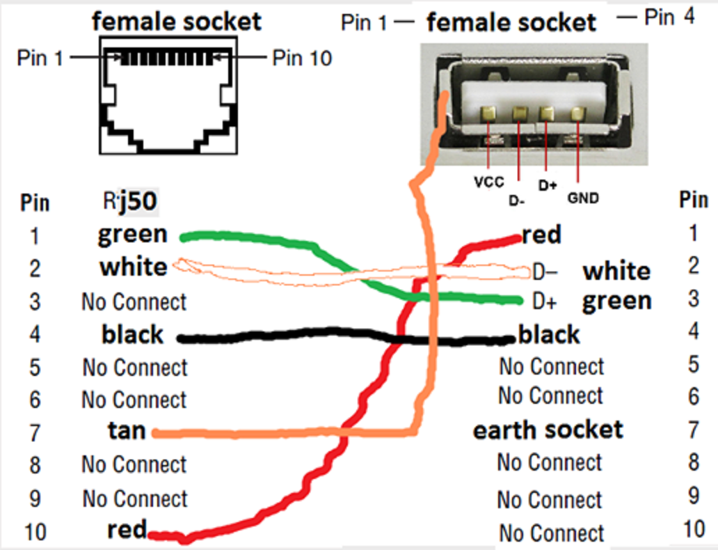
Description: USB wiring is simple but not that simple this is because on changing the frame of reference the pinout looks changed. It can be noticed that pin-out the front side be different than that of back side and thus it requires to check the connectivity of both ends with a digital multi-meter (above micro USB pinout made it simple for you).
Usb Schematic Wiring Diagram
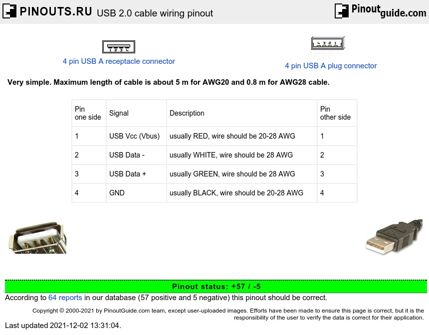
The USB wiring diagram illustrates the physical layout and connections of the wires within a USB cable. It consists of four wires: two power wires (5V and ground) and two data wires (D+ and D-). These wires are responsible for transmitting power and data signals between devices.
USB cable wiring pinout diagram
Wiring Diagram Usb - Wiring Digital and Schematic Wiring Diagram Usb March 30, 2022 by Wiring Digital Understanding Wiring Diagrams for USB Connections When it comes to connecting different devices, the Universal Serial Bus (USB) is one of the most widely used interfaces.

7 Pin Usb Wiring Schematic
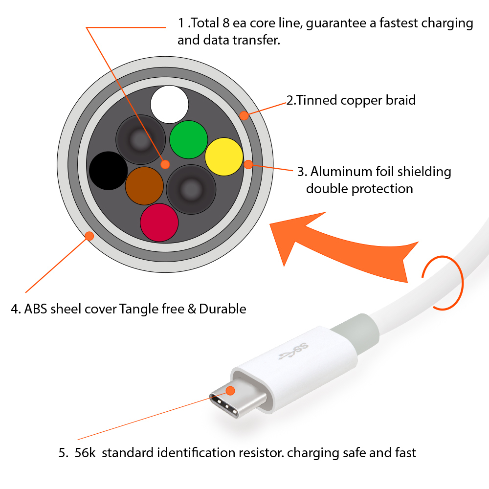
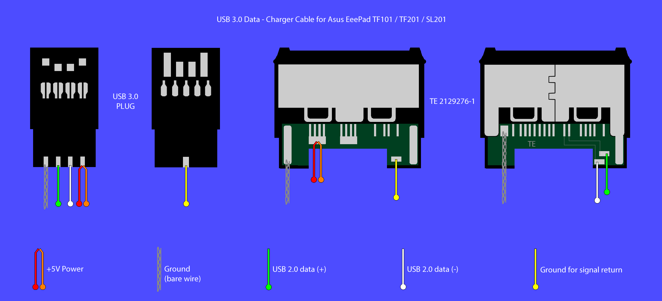
The USB Type C pinout consists of 24 pins, each serving a specific purpose. These pins are organized into four groups: power pins, USB 2.0 data pins, USB 3.1 data pins, and configuration pins. Power Pins: Pins 1 and 4 are used for power delivery. Pin 1 is designated as Vbus, which carries power from the source (e.g., a charger) to the device.

Usb Wiring Schematic
A USB charger circuit ouputs a regulated 5V that can be used to power USB devices or even charge mobile phones and other devices. We will step through this build in 4 phases of construction: Voltage Step Down - First thing we have to do is step the voltage down from 120 volts AC to something low enough we can work with.
USB Wiring Code Wiring Diagram
The USB wiring diagram on a motherboard typically includes information about the USB version supported (such as USB 2.0 or USB 3.0), the pin layout for each USB port, and the power and data connections. The diagram may also indicate which ports are capable of charging devices and which ports are for data transfer only.
USB Wiring Diagram Wires Wiring Diagram
The second wire is the D+ wire, which carries the positive data signal. The third wire is the D- wire, which carries the negative data signal. The fourth wire is the GND (Ground) wire, which provides the reference voltage for the data signals. The USB cable schematic diagram illustrates the arrangement of these wires and their connections.
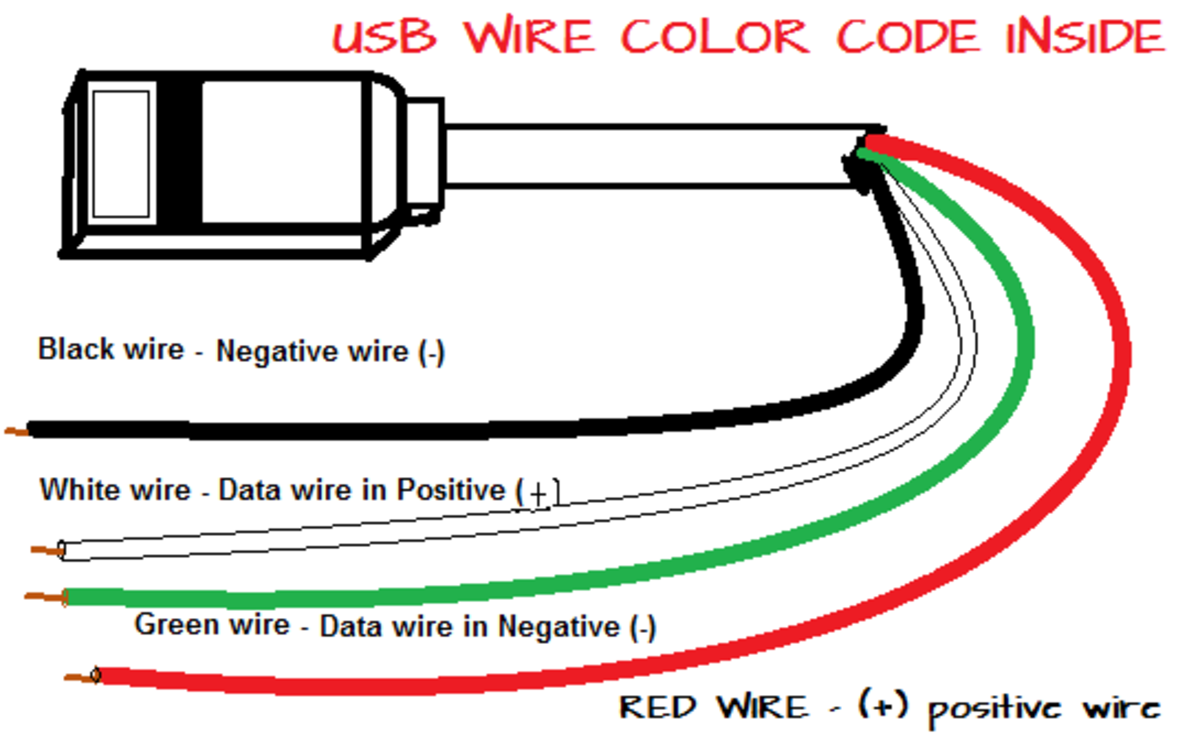
What are the color coding of the four USB wires inside a USB cable or cord
March 10, 2022 by Blessy C Simon Universal Serial Bus (USB) is an electronic device that gives us a universal medium for connecting peripherals. It can be a keyboard, printer, speaker, a storage device, or a mobile phone. With time, USBs have evolved in type, functionality, and efficiency.

Wiring For Usb Cable
A USB connector is the socket, port, or jack into which the plug end of a USB cable or USB-powered device is inserted. USB connectors are typically female, while the USB plug on the cable is male. Rectangular, slot-shaped USB type-A connectors are most common and can be found on computers, personal electronics, and peripherals.

Wiring For Usb Cable
USB stands for Universal Serial Bus and has since replaced its predecessors (FireWire, RS-232 serial, and even parallel) as the primary interface for connecting a host to a device. Normally, the architecture of a USB system includes a host controller, USB ports, and a wide variety of devices.
A V To Usb Wiring Schematic
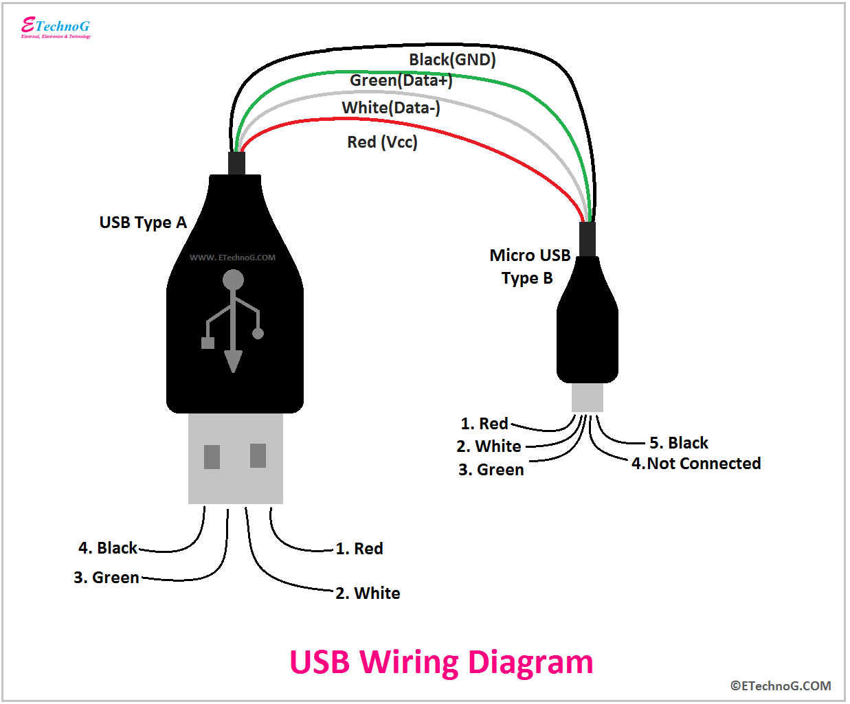
USB Pinout Diagram. A USB cable's wiring and connections can be visualized with the help of a pinout diagram. Type-A, Type-B, Mini-USB, Micro-USB, and USB-C are just a few of the varieties of USB connectors available. Pinout diagrams, which display the configuration and functionality of connectors, are specific to each variety. USB Pinout: Type-A
multi usb port circuit diagram Wiring Diagram
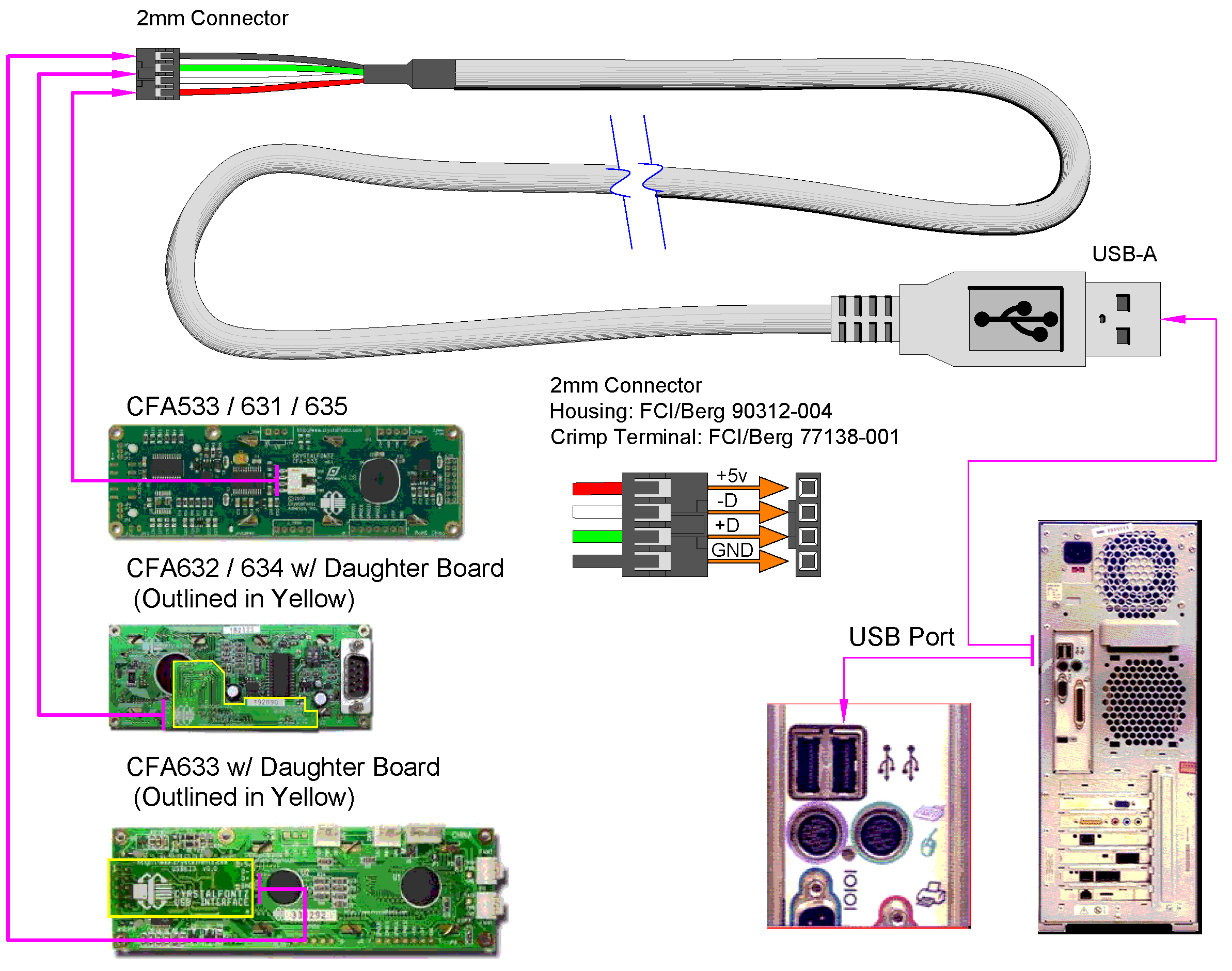
The wiring schematic of USB cables consists of four wires: power, ground, data-, and data+. Each wire plays a vital role in ensuring the proper functioning of the USB connection. The power wire, often colored red, is responsible for delivering power from the USB port to the connected device. The ground wire, typically black or white, serves as.

USB Wiring Diagram, Connection, PinOut, Terminals ETechnoG
19 Nov 2018 Of the five types of USB connectors, Type B is the original "standard" USB connector for peripherals. Today, it's still commonly used to connect printers to other devices where space isn't an issue. What is USB Type B?
